1 Technical Specification
1.1 Feature
- Measure multiple parameters of single-phase AC equipment, such as voltage, current, power, etc.
- Apply the dedicated measuring chip with high precision
- Support wireless 802.11 b/g/n protocol
- 1 RS-485 port
- Support standard MODBUS-RTU, good compatibility and easy programming
- ESD Protection
- Wide operating voltage AC80~265V,
- Reverse connection protection
- High isolation voltage, DC2000V withstand voltage
1.2 Technical parameters
1.2.1 Single-phase AC input
- Voltage Range: 100V, 220V
- Current Range: 5A、50A、100A
- Signal Processing: applies dedicated measuring chip, 24bit AD sample
- Overload Capacity: Not damaged under 5 times current, 1.2 times voltage within 20mS
- Input Impedance: Voltage channel>1 kΩ/V;Current Channel≤100mΩ
1.2.2 Communication interface
- Interface:RS-485
- Protocol:MODBUS-RTU;
- Data format:“n,8,1”;
- Baud rate:1200、2400、4800、9600Bps;9600Bps by default;
1.2.3 Data Output
Voltage, Current, Power, Energy, Power Factor, Frequency
1.2.4 Precision
- Voltage、Current、Energy:±1.0%;
- Active Power: Class 1
1.2.5 Isolation
- Isolation Voltage: 2000VDC;
- Communication port is isolated with power input port
1.2.6 AC Input
- Voltage Range: 100V-220V
- Current Range: 5A-100A
- Peak voltage: not exceeds 265V;
- Typical power consumption:≤2W;(220VAC input)
1.2.7 Work Environment
- Working Temperature: -20~+70℃;Storage Temperature:-40~+85℃;
- Absolute Humidity:5~95%;
- Altitude:0~3000m;
1.2.8 Temperature Drift
- Temperature Drift≤100ppm/℃;
1.2.9 Product Size
- Product Size: 90×36.5×58mm
1.2.10 W-Fi Parameters
- UART baud rate:9600/8/n/1
- Support WiFi 802.11b/g/n, Wi-Fi frequency 1-13
- Wi-Fi transmit power: 18.5dBm@11b,15.5dBm@11g,14.5dBm@11n;
- Wi-Fi frequency: 2.400~2.472GHZ
- Highest transmit speed: 3686400bps
- Support WiFi-DuSL Mode;
- Maximum connections:8
- Support WEB;
- Embedded PCB Antenna, support IPEX external antenna
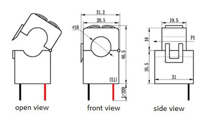
3 C/T Dimensions
The dimension of CT is shown as figure3(Unit: mm)
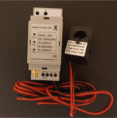
4 Terminals
- Wire the electricity wire connect to terminal UL(Live)and UN(Neutral) for voltage measurement;
- The live wire must go through the hole of C/T (according to the current direction marked at the bottom of C/T )
- RS-485 interface has two terminals, terminal A is positive,B is negative;
4 Indicator
There are three indicators in the front panel,”RUN”, “REV” and “WiFi”; - RUN:Always on after powering on,flashing while the WiFi module is communicating with the power meter;
- REV:Always on when the current is reversed
- WIFI:Always on after the Wi-Fi module is connected to the router